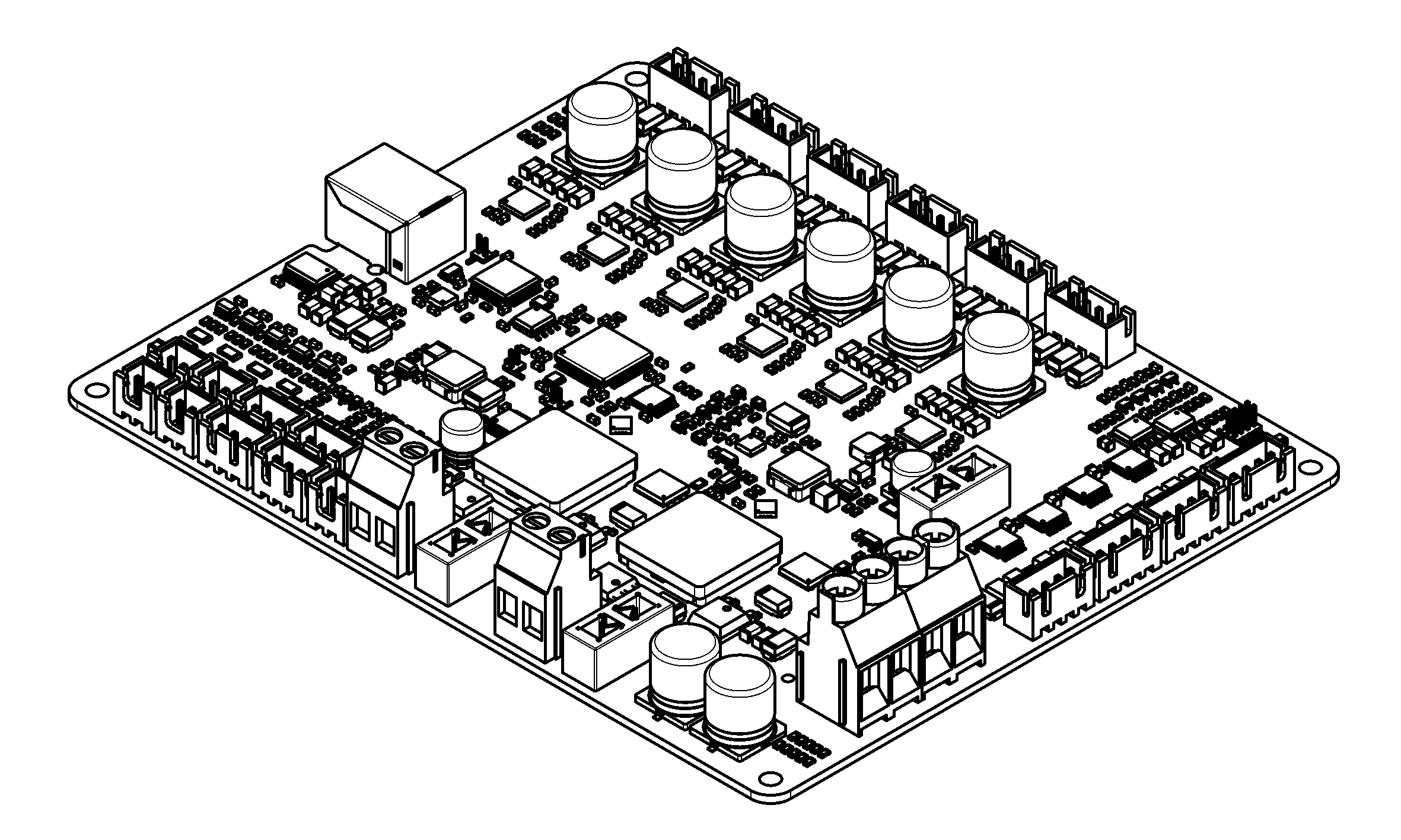
Prunt Board 3
Sign up to be notified when this board is available from CrowdSupply: https://www.crowdsupply.com/prunt-3d/prunt-board-3
Features
- 6× TMC2240 stepper drivers, all capable of running at 3A with minimal airflow
- 2× 15A heater outputs with true short circuit protection that protects the board
- 4× fan outputs, supporting 2, 3, and 4-pin fans, all up to 2A with short circuit protection
- 4× thermistor inputs supporting PT1000 and most common NTC thermistors with protection against shorts to other wires, including heaters
- 4× endstop inputs with protection against shorts to other wires
- Fully isolated USB to protect upstream devices
- Hardware-powered step generation for precise timings and step rates
- Hardware counters for high-speed fan tachometers
- Robust ESD protection
- Buffered thermistor inputs to reduce noise and increase maximum ADC sample rate
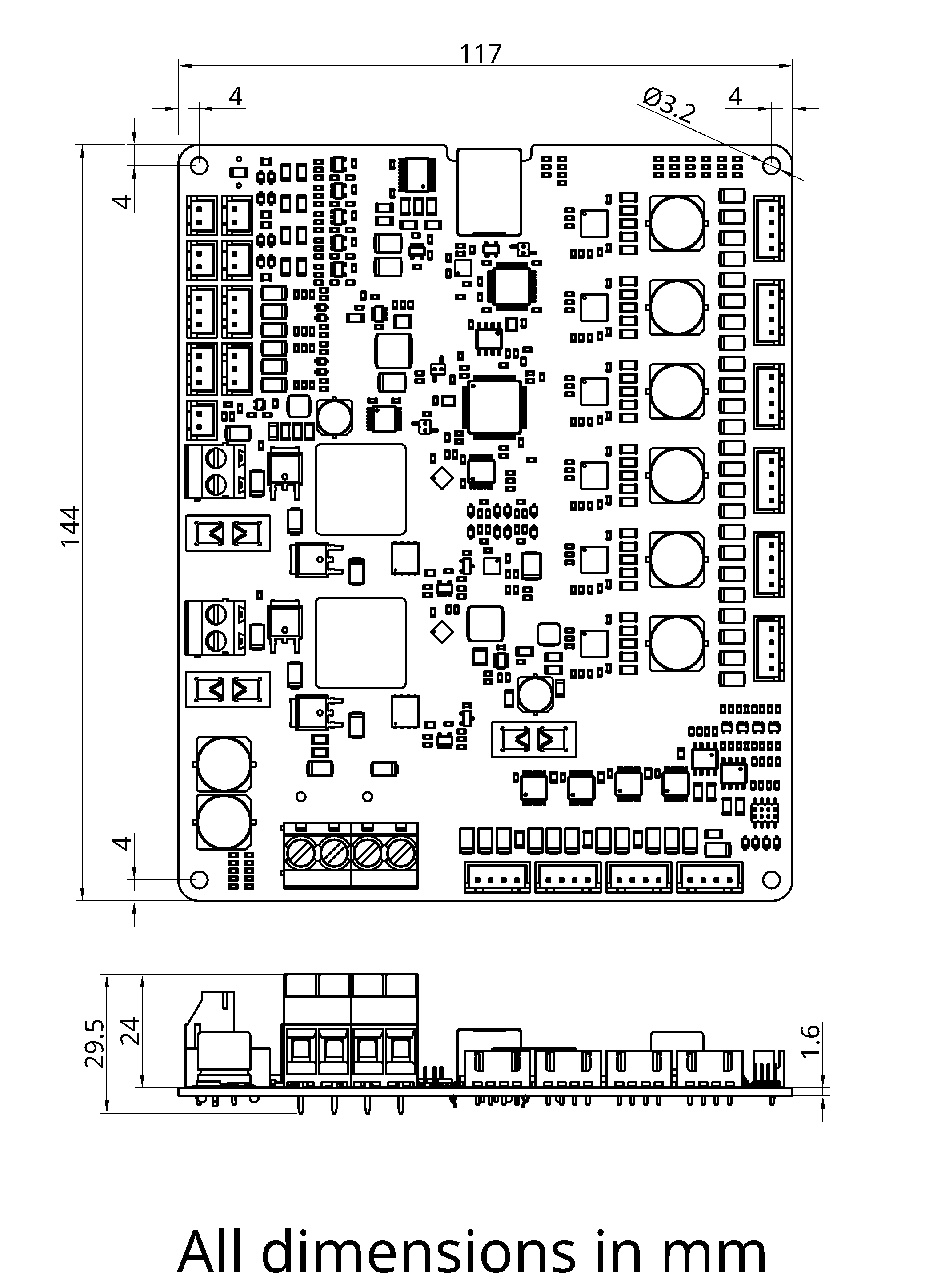
Dimensions
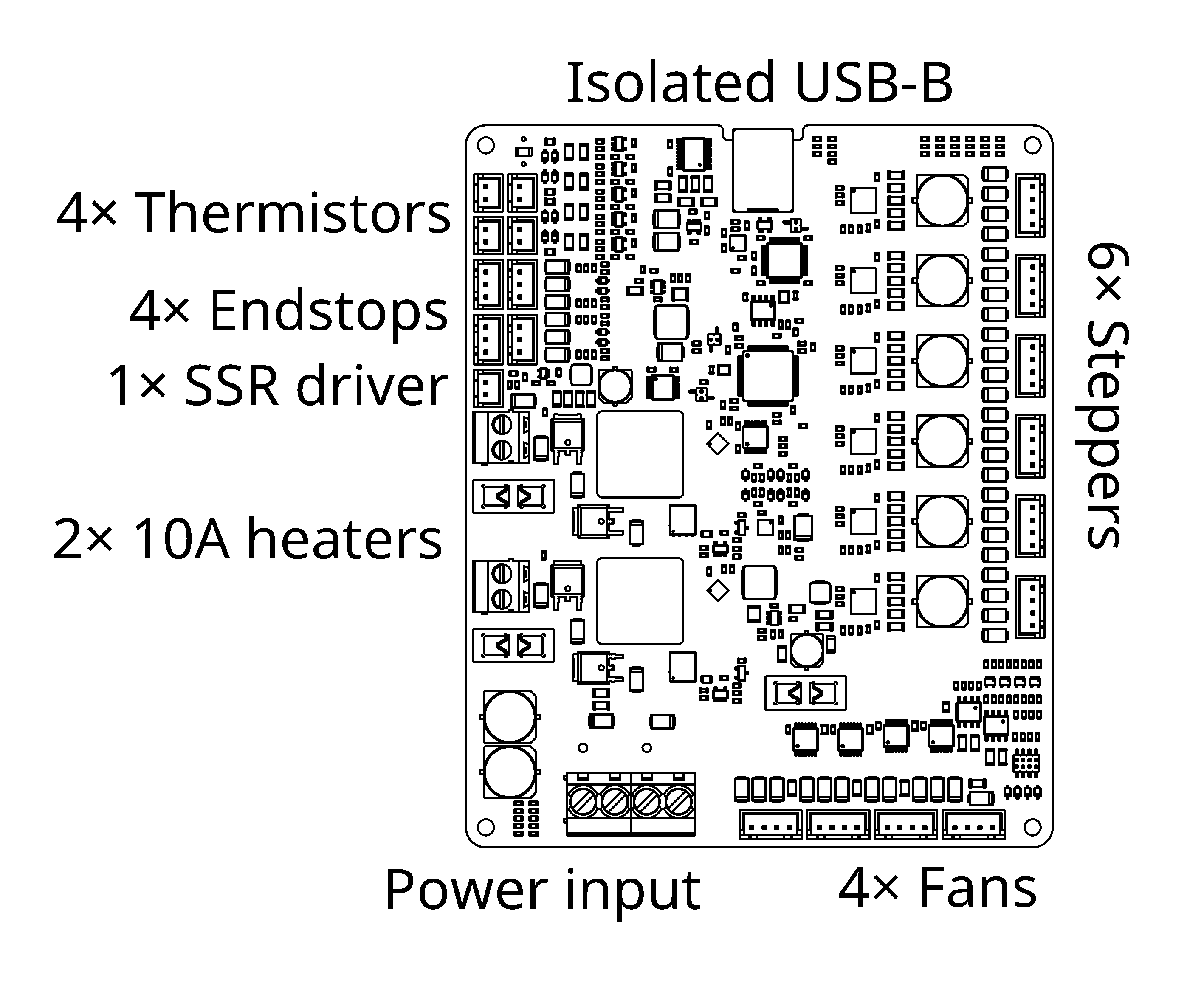
Connectors
USB
The USB port connects to and powers a 6Mb/s USB-UART adaptor with an electrically isolated connection to the rest of the board.
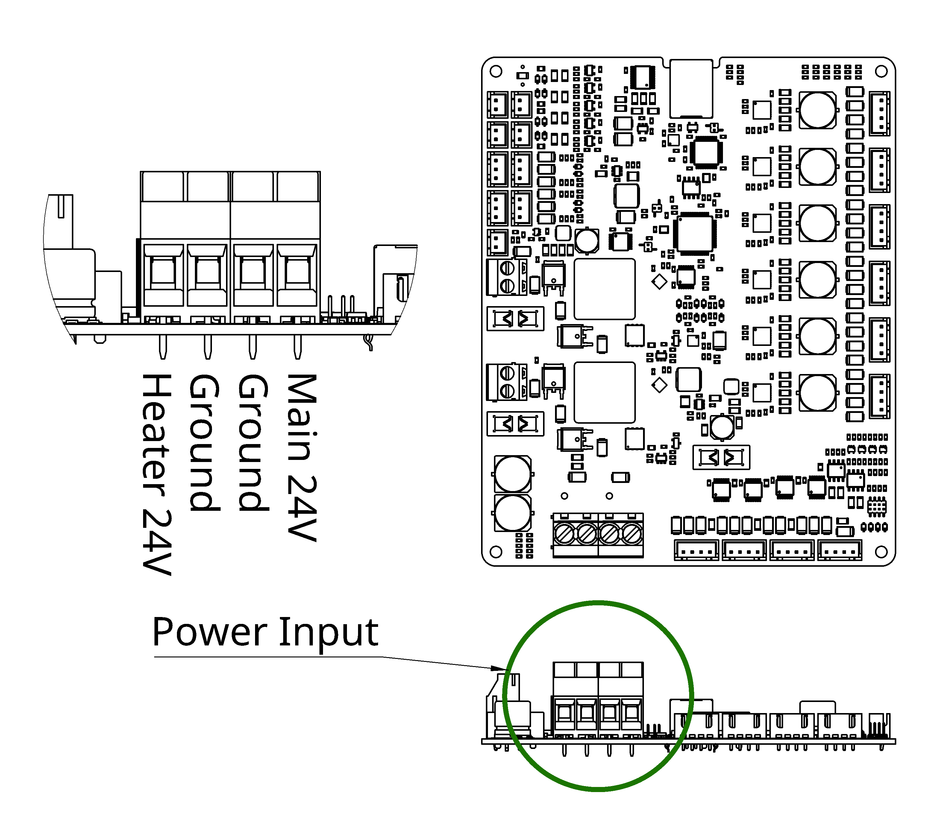
Power
The power supply screw terminals support solid or stranded wires of 24-11AWG / 0.25-4mm² stripped to 8mm and should be torqued to 0.5-0.6Nm.
The board may be powered from a 12-24V power supply.
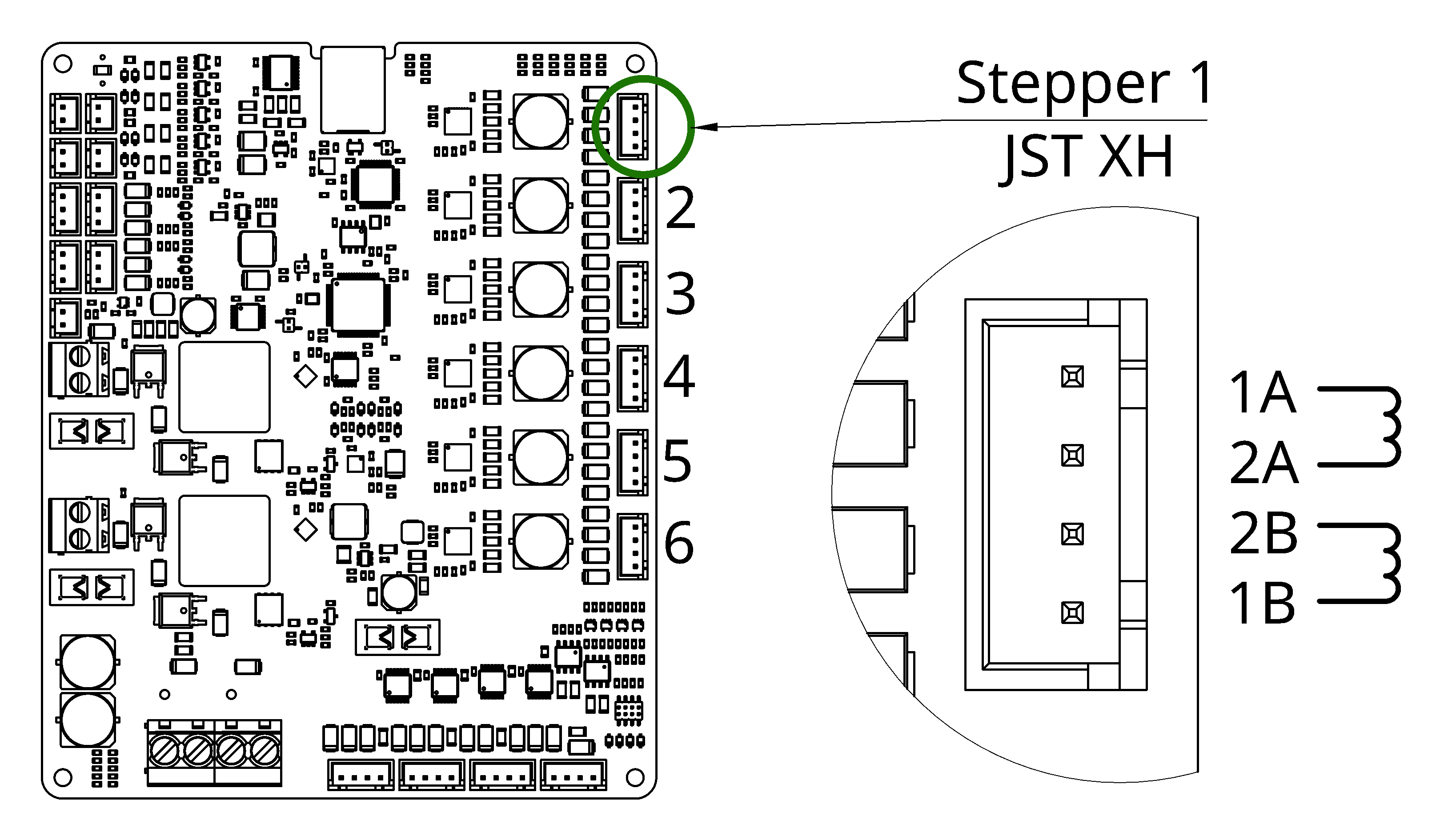
Steppers
Note that the stepper pinout is different from some other boards, specifically each stepper phase should be connected to two adjacent pins.
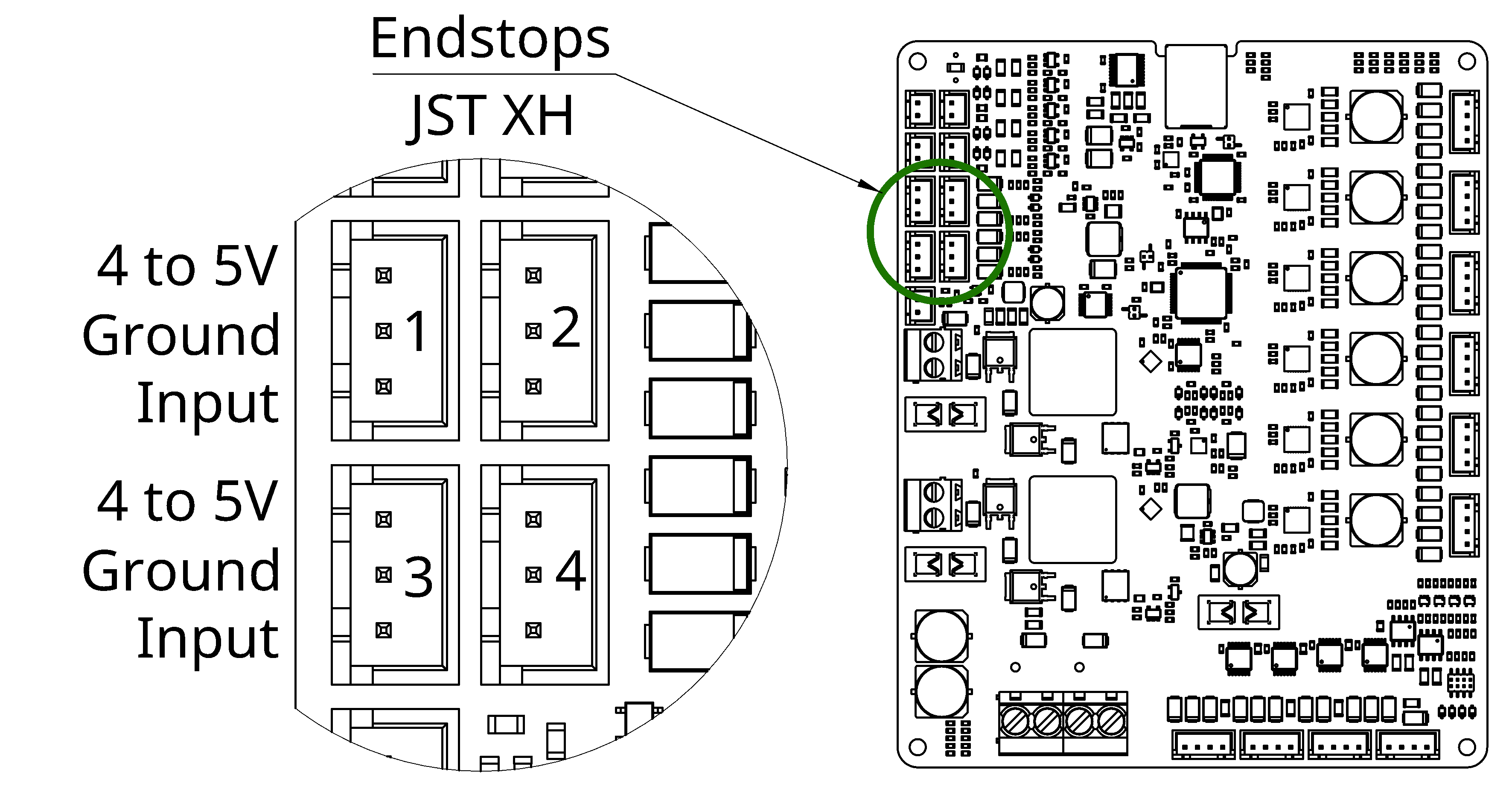
Endstop Inputs
There is a 1A shared current limit between the 4 endstop inputs. Input pins are connected to the power pins via 6.6kΩ resistors. Voltages above 5V should not be applied to the input or 5V pins as this will increase the voltage to all other endstop pins, the board will not be damaged by this but other endstops may be if they are not designed to handle this.
Note that the pinout of endstop connectors varies between different board vendors, refer to the below image and check that your endstops are correctly wired for this pinout.
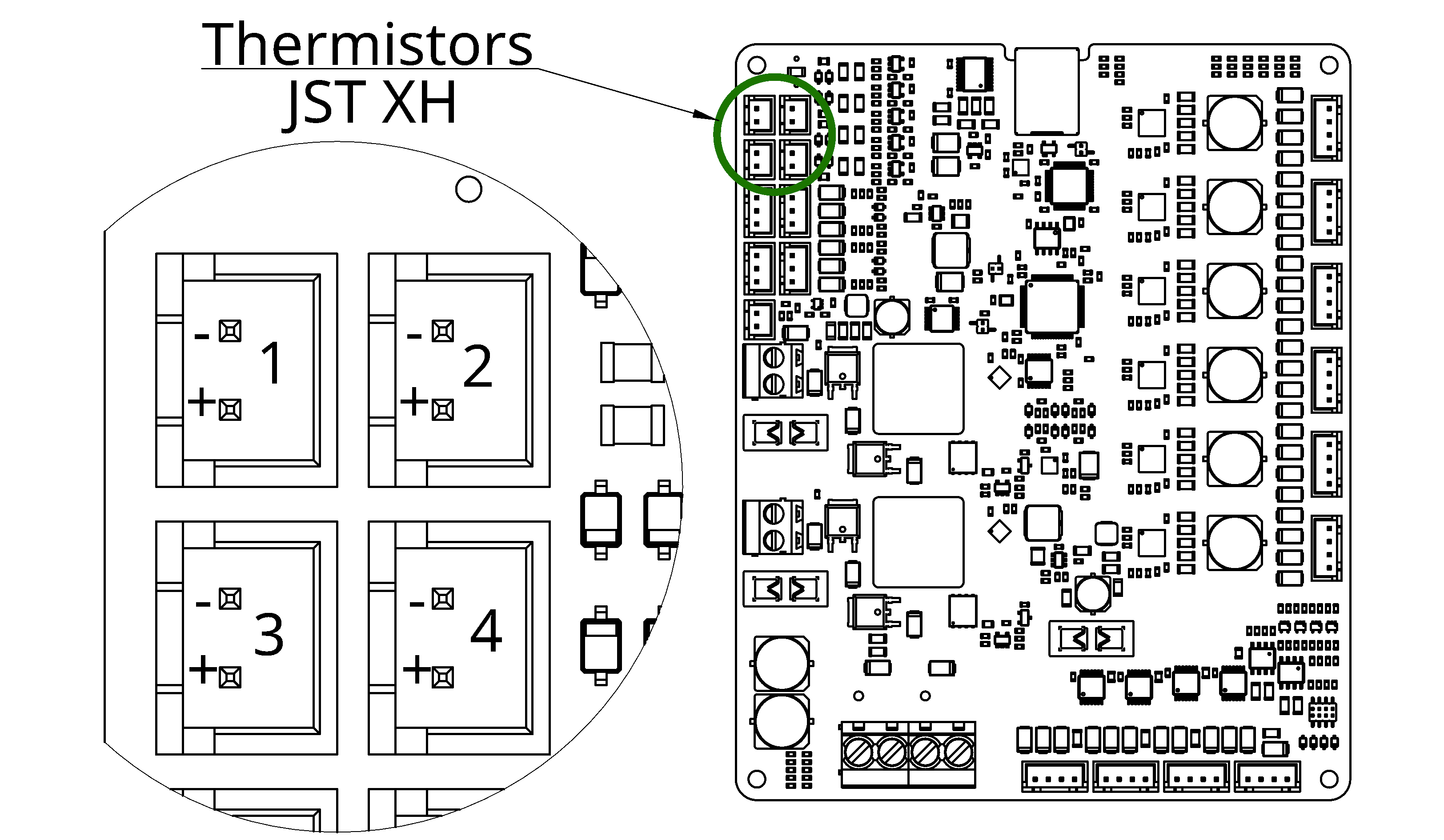
Thermistor Inputs
The thermistor inputs use a 2kΩ pull-up to 3.3V. Most common thermistors, including PT-1000s, may be connected directly as this board contains extra circuitry to allow for lower noise readings than other boards. The thermistor inputs contain protection to prevent damage if any single thermistor is shorted to a heater wire, although the thermistor itself may still be damaged so this should be avoided.
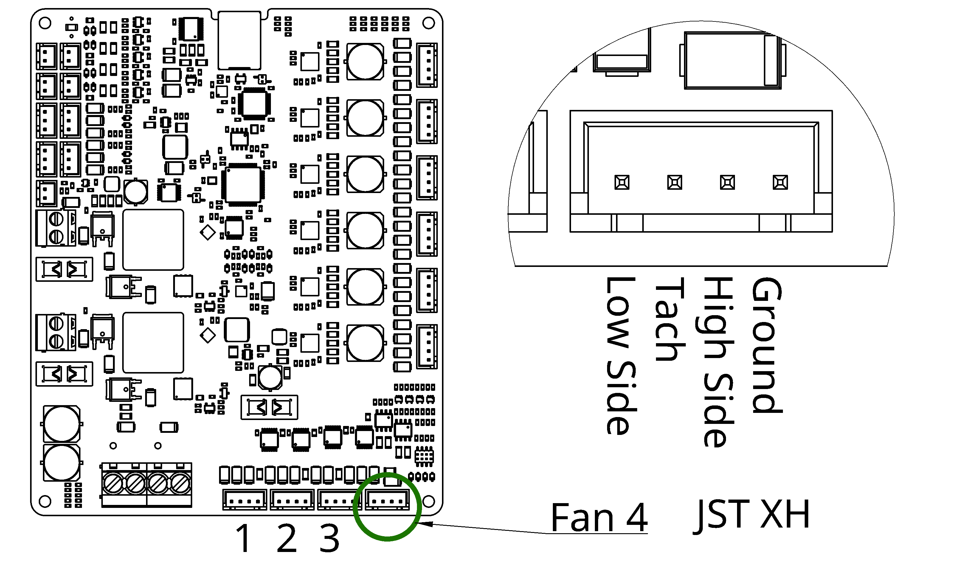
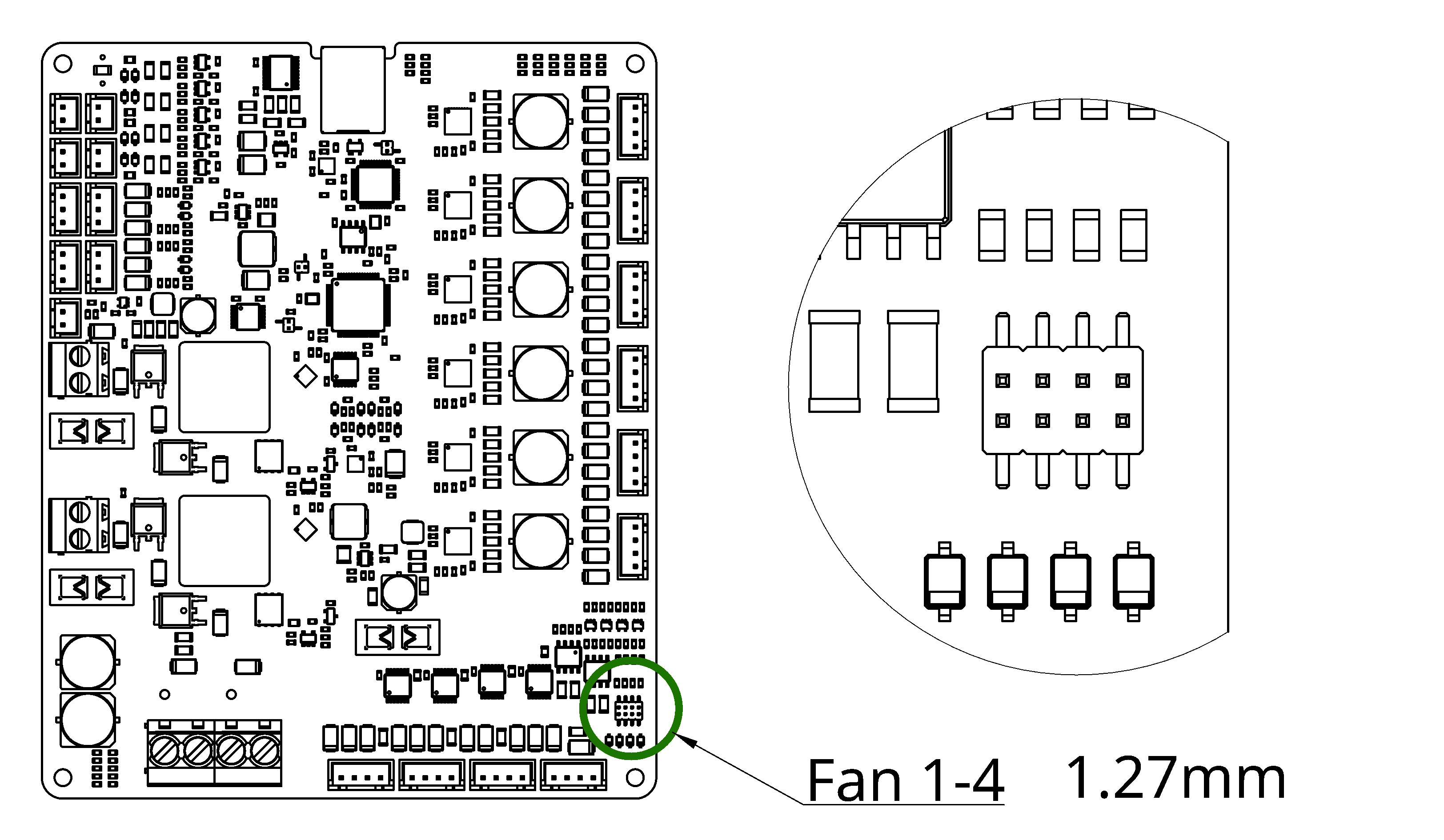
Fans
The high side switch on this fan is capable of driving a 2A load at up to 100Hz. The high side switch is on by default before the board setup runs or when low side switching is selected, this allows it to be used as the power pin when using low side switching.
The low side switch is capable of driving a 500mA load at up to 25kHz. This switch may be used for fans that require a high PWM frequency or it may be used to drive the PWM pin of a 4 wire fan.
The tachometer has a 4.7kΩ pull-up resistor to 5V and can tolerate higher voltages so it can be directly connected to the tachometer output of most fans. The maximum tachometer input rate is limited by hardware to approximately 1kHz. The tachometer should not be used if the low side switch is being used to drive the ground pin of a fan rather than the PWM pin as this may cause damage to the fan.
A 1kΩ pull-up resistor to 5V may be enabled for the low side driver of each fan by installing a 1.27mm in the vertical position on the header. This is useful for fans with a PWM pin which do not contain an internal pull-up, but it should not be used otherwise to avoid damage to fans. The jumpers have no effect when in the horizontal position and may be stored in this position when they are not in use. The order of the 4 pairs of vertical pins is the same as the order of the fan connectors, with fan 1 being on the left and fan 4 being on the right.
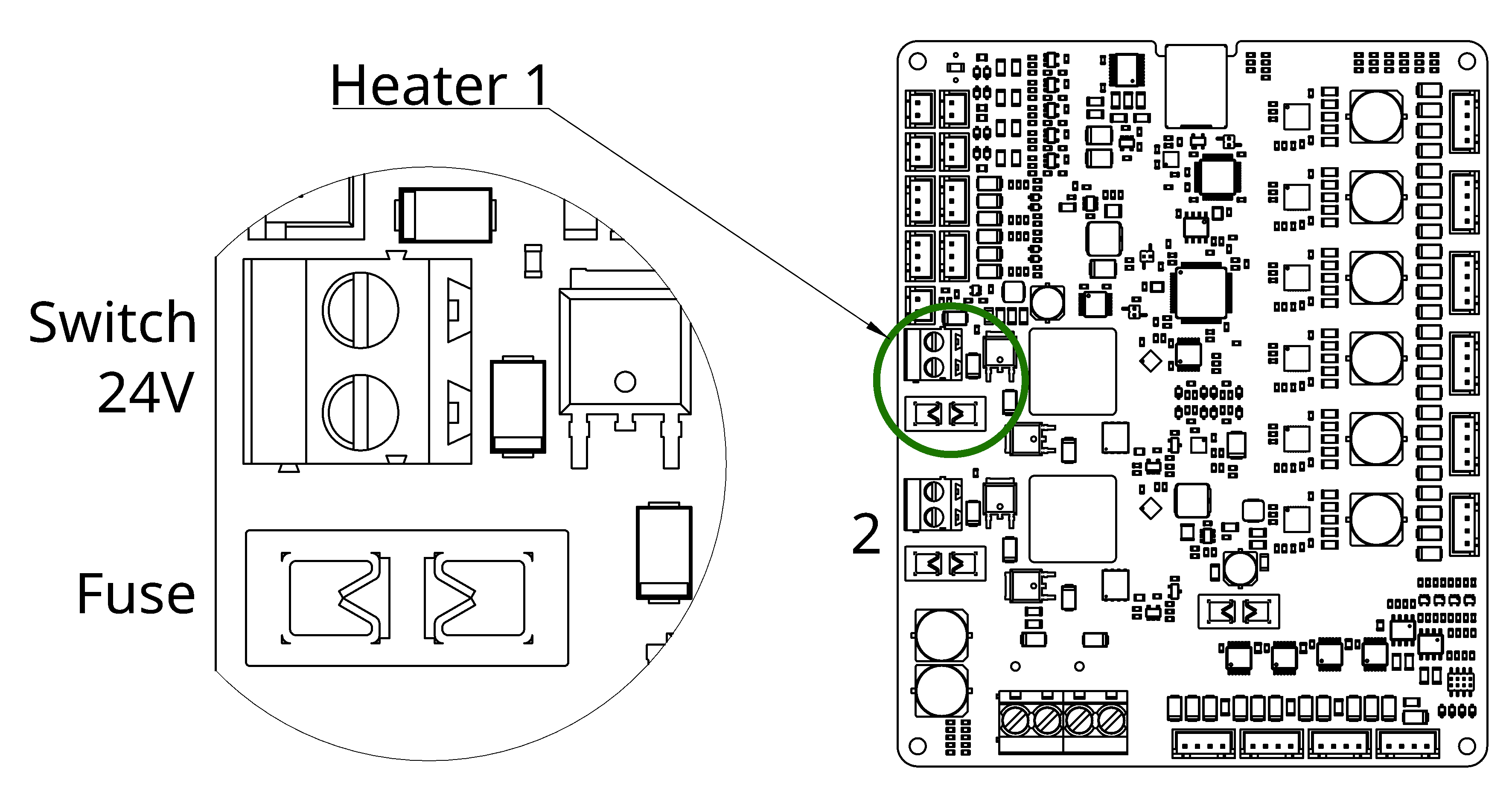
Heaters
The heater screw terminals support solid or stranded wires of 12-26AWG / 0.2-4mm² stripped to 7mm and should be torqued to 0.5Nm.
The heater outputs uses low-side switching at 1kHz and have fast over-current protection which triggers at 15A. If the over-current protection is triggered then the heater output will not turn back on until power to the board has been switched off for 30 seconds. Each heater power pin is protected by a replaceable fuse (10A and 5A by default) to provide some protection if the heater power pin is shorted to a ground pin elsewhere on the board, although this should be avoided.
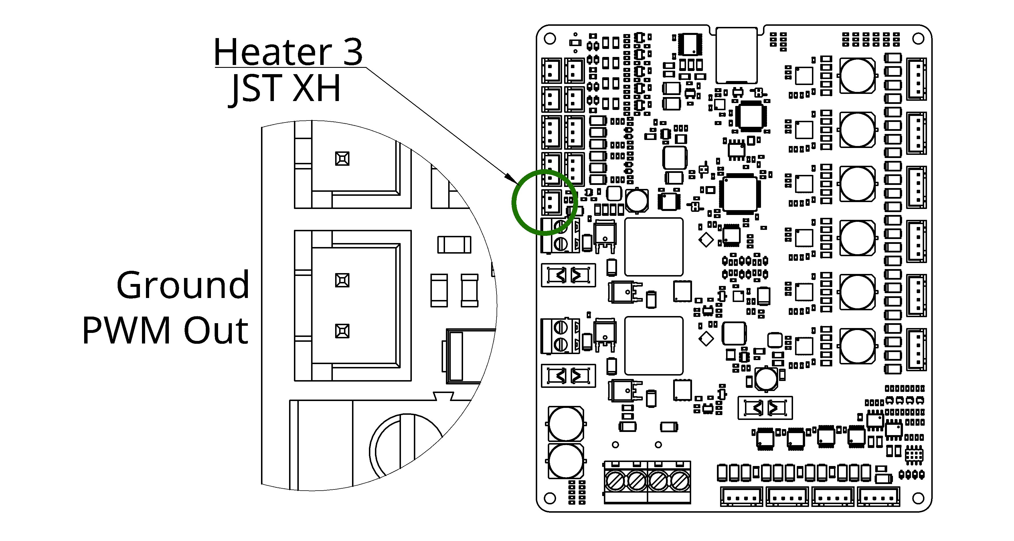
SSR Heater
This heater is designed for controlling an external solid state relay. It outputs a 0V to 5V 1kHz PWM signal through a 500 ohm resistor.
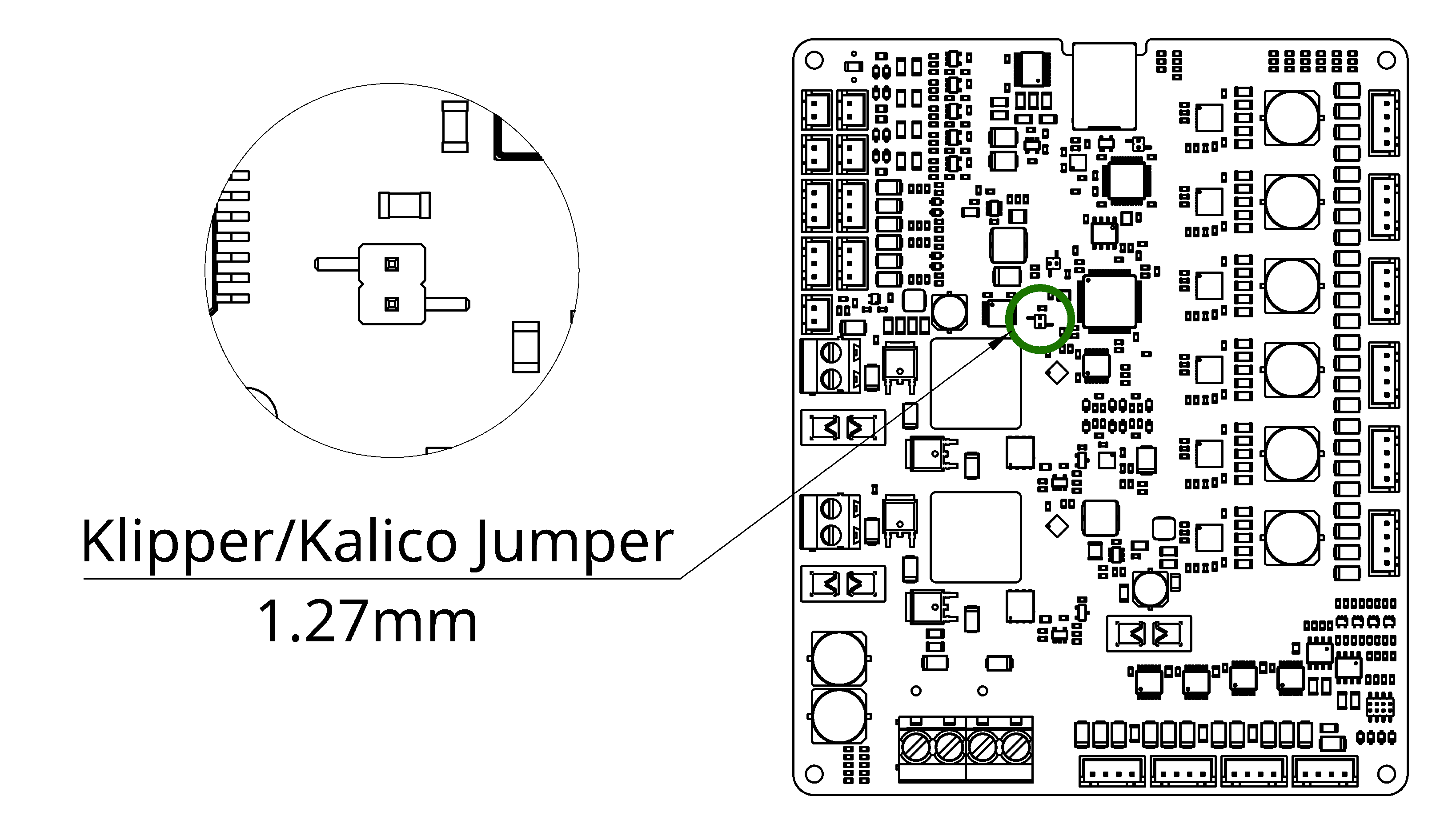
Klipper/Kalico Jumper
prunt_board_3_server --reboot-to-kalico.The board may be switched in to Klipper/Kalico mode by installing a jumper on the pin header shown below. Removing the jumper will return the board back to Prunt mode.
The other two jumpers on the board are used to place the board in flashing mode and are not required for regular use.
When running Klipper or Kalico the pins are referenced by their functions rather than PA1/PA2/etc.. The available pins are:
GPIO_THERMISTOR_1throughGPIO_THERMISTOR_4: All thermistor outputs act as if they have a 4.7k pull-up and no other circuitry, ignore the schematic.GPIO_STEPPER_STEP_1throughGPIO_STEPPER_STEP_6GPIO_STEPPER_DIR_1throughGPIO_STEPPER_DIR_6GPIO_HEATER_PWM_1throughGPIO_HEATER_PWM_2: THESE PINS ARE INVERTEDGPIO_ENDSTOP_1throughGPIO_ENDSTOP_4GPIO_FAN_HS_1throughGPIO_FAN_HS_4GPIO_FAN_LS_1throughGPIO_FAN_LS_4GPIO_FAN_TACH_1throughGPIO_FAN_TACH_4GPIO_TMC_UART
GPIO_HEATER_PWM_1 and GPIO_HEATER_PWM_2 are inverted.
Use !GPIO_HEATER_PWM_N in your configuration, with an exclamation mark at the start.
If you do not include an exclamation mark then any heaters you reference will be permanently on.Basic Setup
Prunt requires a host computer running Linux, we do not currently have a guide for setting one up. If you already use MainsailOS or similar then there’s no need to switch to a different OS as the Prunt server is a single binary that will run on most Linux based operating systems.
- Connect the board to the various motors/thermistors/etc.
- On the host machine, download the server binary from https://github.com/Prunt3D/prunt_board_3_software/releases (on a Raspberry Pi use the aarch64 version, on a Intel-powered mini PC or desktop use the x64 version)
- Run
chmod +x ./prunt_board_3_serverto make the server binary executable - Run the server as
./prunt_board_3_server, add the CPU assignment flags detailed below if using CPU isolation - Navigate to <host_address>:8080 in a web browser
- Navigate to “Configuration” at the top of the page
- Go through each tab and configure the board as desired using the built-in descriptions
- Finally navigate to the Prunt tab in the config editor and tick the box to enable Prunt and save
- Go back to the status page and click “Reload Server”
Details on slicer settings may be found here.
CPU Isolation
We recommend setting up CPU isolation for two CPU cores to increase reliability under high system loads, but this is not required and we have yet to run in to any issues during testing where we don’t use CPU isolation.
CPU isolation prevents any tasks from running on a given CPU if they are not assigned to that specific CPU. This is useful for Prunt as it can prevent other tasks from taking away resources from the time-sensitive step generator task.
Example of parameters to isolate the third and fourth CPU: nohz=on nohz_full=2,3 rcu_nocbs=2,3 isolcpus=nohz,domain,managed_irq,2,3 rcu_nocb_poll
To add these parameters on OpenSUSE or SUSE: Run yast2, navigate to boot loader > kernel parameters, and append the parameters to the existing parameters.
To add these parameters on Raspberry Pi OS: Edit /boot/cmdline.txt and append the parameters to the existing parameters.
Note that CPUs in Prunt start from 1 whereas CPUs in Linux start from 0, therefore for the above parameters 3 or 4 should be passed to Prunt rather than 2 or 3.
To use these CPUs with Prunt simply run the server binary with the extra command line flags: --prunt-step-generator-cpu=3 --communications-cpu=4.